How to create a level 0 data flow diagram dfd
Table of Contents
Table of Contents
If you’re looking to create a system model to represent complex data flow or information flow, then you’re in the right place. Drawing DFD Level 0 Diagram is one of the important aspects of system modeling that represents the flow of data in a system.
Many people find it challenging to create a DFD Level 0 Diagram. This system diagram defines the context of your system, thinking about what the system will accomplish and what inputs and outputs will be needed.
How to draw DFD Level 0 Diagram and its target?
Creating a DFD Level 0 Diagram is not difficult if you follow certain steps. First, you need to understand what the system is doing, and then you need to understand what type of data it is handling. Once you have answers to these two questions, you can move on to drawing the diagram. In general, the target of drawing a DFD Level 0 Diagram is to show how the data flows through the system and how the system is processing the data.
Here are the main points to follow when creating a DFD Level 0 Diagram:
- Start by defining the system boundaries
- Identify external entities
- Identify the main processes
- Connect the processes with data flows
- Add data stores, where appropriate
My experience with DFD Level 0 Diagram
As a software engineer, I’ve had the opportunity to work on various system modeling projects. One of the projects required me to create a DFD Level 0 Diagram. At first, I found it slightly intimidating, but once I understood the steps involved, it became much easier. The result was a clear picture of how data flowed through the system and what processes were involved in processing the data.
When defining the system boundaries, we considered what the system’s inputs and outputs would be, as well as the external entities that interacted with the system. We then identified the core processes that manipulated the data and connected them with data flows. The final diagram represented a clear view of how data flowed in the system and what other entities interacted with the system.
Tips for drawing DFD Level 0 Diagram
While drawing a DFD Level 0 Diagram, here are some tips to consider:
- Start with the system boundaries and clearly define the inputs and outputs.
- Identify the external entities and distinguish between them and the internal entities.
- Identify the main processes that manipulate the data.
- Connect the processes with the data flows.
- Keep the diagram simple and easy to understand.
Additional Points to Consider
It is important to note that while creating a DFD Level 0 Diagram, you should keep the diagram up-to-date with the latest version of the system. You can use different colors or shapes to distinguish between external entities and internal entities, but keep it consistent throughout the diagram. Lastly, be prepared to iterate on the diagram several times before finalizing it.
Common Mistakes to Avoid
Here are some common mistakes to avoid when creating a DFD Level 0 Diagram:
- Not clearly defining system boundaries or inputs/outputs
- Confusing external entities with internal entities
- Complicating the diagram with too many processes or data flows
- Including unnecessary data stores in the diagram
Question and Answer Section
What is a DFD Level 0 Diagram?
A DFD Level 0 Diagram is a system model that defines the context of the system and shows how data flows in the system and how the system is processing the data.
What are the main steps to follow when creating a DFD Level 0 Diagram?
The main steps to follow when creating a DFD Level 0 Diagram include defining the system boundaries, identifying external entities, identifying the main processes, connecting the processes with data flows, and adding data stores, where appropriate.
What are some tips for drawing a DFD Level 0 Diagram?
Some tips to consider when drawing a DFD Level 0 Diagram include starting with the system boundaries, clearly defining inputs and outputs, identifying external entities, distinguishing between external and internal entities, keeping the diagram simple and easy to understand, and being prepared to iterate on the diagram several times before finalizing it.
What are some common mistakes to avoid when creating a DFD Level 0 Diagram?
Some common mistakes to avoid when creating a DFD Level 0 Diagram include not clearly defining system boundaries or inputs/outputs, confusing external entities with internal entities, complicating the diagram with too many processes or data flows, and including unnecessary data stores in the diagram.
Conclusion of How to Draw DFD Level 0 Diagram
Creating a DFD Level 0 Diagram may seem like a daunting task at first, but once you understand the main steps and tips outlined above, it becomes much easier. Keep in mind that the target is to show how data flows through the system and how the system processes the data. By following the above steps and tips, you can create a clear and concise DFD Level 0 Diagram that will help you in system modeling.
Gallery
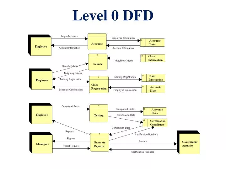
PPT - Level 0 DFD PowerPoint Presentation, Free Download - ID:6882153

Photo Credit by: bing.com / dfd level slideserve
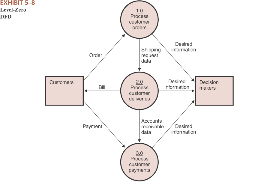
How To Create A Level-0 Data Flow Diagram (DFD) - YouTube

Photo Credit by: bing.com / dfd
Codelybrary: DFD In Software Engineering

Photo Credit by: bing.com / dfd diagrams dfds example1 eternal sunshine
Diagram 0 Dfd - Wiring Diagram

Photo Credit by: bing.com /
DFD Level 0 Diagram | Download Scientific Diagram

Photo Credit by: bing.com / dfd diagram


