Solved draw the logic circuit represented by each expression
Table of Contents
Table of Contents
If you’re interested in the world of electronics, you may have wondered how to draw a logic circuit. Perhaps you have a project in mind or just want to understand how electrical systems work. Whatever your reason may be, the ability to draw a logic circuit is a valuable skill to have.
When learning how to draw a logic circuit, many people find it difficult to know where to start. They may feel overwhelmed by the task or intimidated by technical diagrams. Additionally, there may be confusion surrounding the symbols and conventions used in electronic diagrams. Despite these challenges, drawing a logic circuit is not as difficult as it may seem.
The first step in drawing a logic circuit is to understand the basics of electrical systems. Electrical circuits consist of various components that interact to perform specific functions. These components include resistors, capacitors, diodes, transistors, and many others. Logic circuits, on the other hand, focus on the interaction of logic gates.
Logic gates are the building blocks of logic circuits. They are electronic components that perform logical operations on one or more binary inputs to produce a single binary output. Some common types of logic gates include AND, OR, NOT, and XOR gates. Once you understand these basic concepts, you can begin to draw your logic circuit.
My experience with drawing a logic circuit
When I first started learning how to draw a logic circuit, I found the process quite confusing. It was challenging to understand the different symbols and how they related to one another. However, with practice and patience, I began to understand the components and how they interacted with one another. Now, I feel confident in my ability to create logic circuits and troubleshoot problems when they arise.
Understanding logic gates and symbols
The first step in drawing a logic circuit is to understand the symbols used for various logic gates. AND gates are represented by a dot or an intersection of lines, while OR gates are represented by a plus sign. NOT gates are represented by a triangle with a circle at the end, and XOR gates are represented by a circle with a plus sign inside.
Once you understand the symbols, you can begin to create your circuit. Start by drawing the logic gates and connecting them to create the desired circuit. Label your inputs and outputs to keep track of the flow of information. You may also want to include resistors or capacitors in your circuit to regulate the flow of electricity.
Creating a truth table
Before you start drawing your logic circuit, it can be helpful to create a truth table. This table lists all possible inputs and outputs for a logic circuit. It can help you ensure that your circuit functions as intended and identify any errors. Start by listing all possible input combinations and their corresponding outputs. Then, use this table to double-check your circuit as you draw it.
Troubleshooting your circuit
If your circuit is not functioning correctly, there may be a problem with your design. Make sure that your connections are correct and that your components are properly aligned. You may also want to check that your inputs and outputs are labeled correctly. Additionally, test each component of your circuit to ensure that it is functioning correctly.
Conclusion of how to draw a logic circuit
Learning how to draw a logic circuit may seem daunting, but with practice, it can become second nature. By understanding the symbols and conventions used in electric diagrams and logic gates, you can create functional circuits that perform specific tasks. Remember to create a truth table to ensure that your circuit works as intended and troubleshoot any issues as they arise. With time and effort, you can become a proficient logic circuit designer.
Question and Answer
1. What is a logic circuit?
A logic circuit is an electronic circuit that uses logic gates to process information and perform calculations.
2. What are logic gates?
Logic gates are electronic components that perform logical operations on one or more binary inputs to produce a single binary output.
3. What is the purpose of a truth table?
A truth table lists all possible inputs and outputs for a logic circuit. It can help ensure that your circuit functions correctly and identify any errors.
4. How can you troubleshoot a logic circuit?
If your circuit is not functioning correctly, check your connections, ensure your components are properly aligned, test each component of your circuit, and verify that your inputs and outputs are labeled correctly.
Gallery
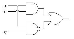
Logic Gate Examples

Photo Credit by: bing.com / logic circuit gate draw boolean ab examples ac problems algebra dic lab work exercise gif sandbox cs110 bennet mc edu
Draw Logic Circuit Diagram For X+Y’Z - Brainly.in

Photo Credit by: bing.com / logic circuit
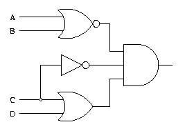
Solved: Draw The Logic Circuit Represented By Each Expression

Photo Credit by: bing.com /
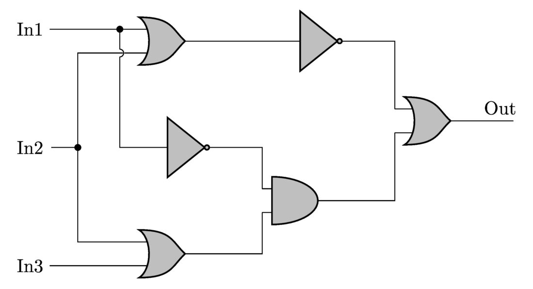
Draw A Logic Circuit In CircuiTikZ - TikZBlog

Photo Credit by: bing.com / circuitikz latexdraw
Logic Gate Examples

Photo Credit by: bing.com / logical gates circuit gate boolean logic example examples questions draw problems simulator algebra problem scan handrawn possible sandbox bennet cs110


